| tags: [ series infrastructure ]
Building a Homelab - Part 2: Networking
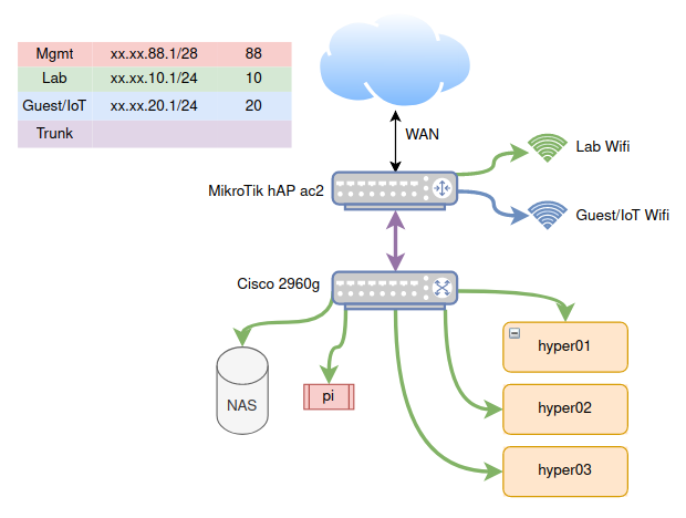
In the previous post, we introduced the beginnings of the makings of a homelab and the hardware I’ll been using for it. In this post, I will be going over the networking I’ve setup to have all pieces talking to each other in a safe and secure way. This networking scheme is simple, and will most likely evolve as I add more services on my hypervisors. Here’s what it looks like:
VLANs
The first thing you’ll notice is a table on the top left with different IP address ranges and colors. These are VLANs. As a short introduction to VLANs: the abbreviation stands for virtual local area networks.1 Normally, if you wanted multiple LANs, you’d use multiple switches, and then connect those switches either together, or through a router. A VLAN allows one to segregate a single switch into multiple virtual switches. We can then separate distinct networks without requiring extra hardware.
In the diagram above, you’ll see that the Cisco 2960g switch has multiple machines attached to it, all on the Lab network. I could just as well set an additional port to be on the Guest VLAN, and then any machine connected to this port would not be able to communicate with the Lab network.
In fact, I do something similar on the MikroTik router. I create two wifi networks: one on the Lab VLAN, and one on the Guest VLAN. Those who are connected to the Lab wifi can access any machine connected to the Lab VLAN, and similarly for the Guest wifi. This ensures there is no cross-talk between the two.2 Why would we do this? Well, often times, a lot of IoT gadgets, like this “smart” toaster, might want to snoop on the network. By segregating them to their own VLAN, they are only allowed see any machines in their network.
Two other colors in the chart shown are the management VLAN and the trunk. Here is a “zoomed-in” diagram of each port mapping on the router and switch above:
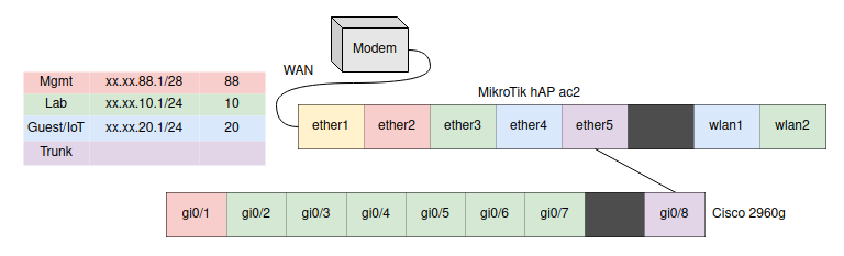
The management VLAN is the only way to configure the router or the switch. For security’s sake, you must be plugged into its assigned port. The trunk port passes through all VLANs, and as can be seen in my configuration, it is attached to the trunk port on the switch. In this way, it is used as a “highway” to pass VLAN-assigned traffic from-and-to the router.
Additional considerations
This network topology is very simple and it makes managing it easier. However, the Cisco switch I am using is an older model I received just to experiment with and I am worried about its reliability. For now, this is fine as I’m not hosting anything critical on it. But it is a central point of failure in my network, and I’d like to eventually replace it with another switch, or just add one more switch and connect the two such that they work as a high-availability pair.
The other issue in this network is that all traffic from the switch goes through a single port to the router. If this port ever goes down for some reason, I lose all connectivity to the lab. Unfortunately, this is only an 8-port switch and I don’t have any extra ports. This gives me more reason to get a second newer switch with more ports, this way I can use multiple ports in a link aggregation group to provide redundancy.
Next step
With the network segregation in place, I am now comfortable experimenting with the lab in an relatively isolated network. We can begin setting up our hardware nodes with Proxmox as our virtualization environment. Tune in next time.
-
I will be skipping the technical aspects of how VLANs are built. For a much more thorough guide on VLANs, I recommend this series of articles. ↩︎
-
By default! One can of course configure this on the router to allow some ability to communicate between VLANs. ↩︎